


Custom inductor manufacturer tells you
What are the reasons that affect the inductance failure of the patch? Today, I have combed some relevant contents for your reference.
Causes of inductor failure
1. The mechanical stress produced by the magnetic core in the machining process is large and has not been released.
2. There are impurities in the magnetic core or the hollow magnetic core material itself is not uniform, which affects the magnetic field condition of the magnetic core and deviates the permeability of the magnetic core.
3. Due to the sintering crack after sintering.
4. When the copper wire is connected with the copper strip by immersion welding, the coil is splashed with liquid tin, melting the insulation of the enamelled wire and causing a short circuit.
5. The copper wire is slender, which results in false welding and open circuit failure when connected with the copper strip.
Welding mode
The inductance of low frequency patch power inductor increases by less than 20% after reflow soldering.
Demagnetization occurs because the temperature of reflow soldering exceeds the Curie temperature of low frequency patch inductor material. After the demagnetization of the patch inductor, the permeability of the patch inductor material returns to the maximum and the inductance increases. The general control range is that the inductance increases by less than 20% after the patch inductor is resistant to welding heat.
The problem that solder resistance may cause is that sometimes the circuit performance is all qualified in small batch manual welding (when the patch inductor is not heated as a whole, the inductance increases slightly). However, when there are a large number of chips, it is found that the performance of some circuits is degraded. This may be due to the increase of the inductance of the patch after reflow soldering, affecting the performance of the circuit. In places where the accuracy of chip inductance is strictly required (such as signal receiving and transmitting circuit), more attention should be paid to the welding resistance of chip inductor.
When the temperature of reflow soldering is reached, the metal silver reacts with the metal tin to form an eutectic, so tin cannot be plated directly on the silver end of the patch inductor. Instead, the silver end is first plated with nickel to form an insulating layer, and then tinned.
1. End oxidation:
When the patch is electrically affected by high temperature, humidity, chemicals, oxidizing gases, or stored for too long, the metal Sn on the inductor end of the patch is oxidized to SnO2, and the inductor end of the patch becomes dark. Because SnO2 does not form eutectic with Sn, Ag, Cu, etc., the solderability of patch inductance decreases. Shelf life of patch inductor products: half a year. If the inductance end of the patch is contaminated, such as oily substances, solvents, etc., it will also cause a decline in solderability.
2. The nickel coating is too thin:
If the nickel plating, the nickel layer is too thin to play the role of isolation. During reflow soldering, the Sn on the inductor end of the patch reacts with its own Ag first, which affects the co-melting of the Sn on the inductor end of the patch and the solder paste on the pad, resulting in the phenomenon of eating silver and the decrease of the solderability of the patch inductor.
Judgment method: dip the patch inductor into the molten solder can for a few seconds and take it out. If the potholes are found at the end, or even the porcelain body is exposed, it can be judged that there is a phenomenon of eating silver.
3. Poor welding:
If the patch inductor product has bending deformation, there will be magnification effect during welding. Poor welding, false welding, improper pad design.
a. Both ends of the pad should be designed to avoid different sizes, otherwise the melting time and wetting force of the two ends will be different.
b. The welding length is above 0.3mm (that is, the coincidence length of the metal end of the patch inductor and the pad).
c. The length of the pad is as small as possible, generally no more than 0.5mm.
d. The width of the pad itself should not be too wide, and its reasonable width should not exceed 0.25mm compared with the width of MLCI.
When the patch inductance shifts the θ angle because of the uneven solder pad or the slip of solder paste. Due to the wetting force produced during the melting of the welding pad, the above three situations may be formed, of which self-correcting is dominant, but sometimes the pull is more oblique, or a single point is pulled, and the patch inductor is pulled onto a pad, or even pulled up. Oblique or upright (monument phenomenon). At present, the placement machine with θ angle offset visual inspection can reduce the occurrence of this kind of failure.
If the rated current of the selected chip inductor beads is small, or if there is a large impulse current in the circuit, the current will burn out and the chip inductor or magnetic beads will fail, resulting in an open circuit. Remove the patch inductor from the circuit board for testing, the patch inductor fails, and sometimes there are signs of burnout. If current burnout occurs, the number of failed products will be more, and the failed products in the same batch will generally reach more than 100%.
The rapid cooling and heating during reflow soldering causes the internal stress of the patch inductor, which leads to the enlargement of the defects of a very small part of the patch inductor which has the hidden danger of open circuit, resulting in the open circuit of the patch inductor. Remove the patch inductor from the circuit board to test, the patch inductor is invalid. If there is a welding open circuit, the number of failed products is generally small, and the failed products in the same batch are generally less than 1000 grades.
Magnet strength
The ceramic body is not strong enough and brittle due to poor sintering of the patch inductor or other reasons, or the porcelain body is damaged when the product is impacted by external force.
Adhesion force
If the adhesion of the silver layer of the inductor end of the patch is poor, when reflow soldering, the inductor of the patch is cold and hot, the stress caused by thermal expansion and cold shrinkage, and the porcelain body is impacted by external forces, it is possible to cause the separation and shedding of the inductor end and the porcelain body; or the pad is too large, and when reflow soldering, the wetting force caused by paste melting and end reaction is greater than the end adhesion, resulting in end damage.
The patch inductor overburns or burns raw, or there are micro-cracks in the manufacturing process. The rapid cooling and heating during reflow soldering causes stress inside the patch inductor, crystal crack, or micro-crack expansion, resulting in magnet damage and so on.
You May Like
Read more news
1. Overview of Inductance Properties
2. Function and Resistance Analysis of Inductance Coil
3. An overview of inductance and capacitance and each current
4. Analysis of inductor current
5. Why is the inductance when the wire is wound in a circle
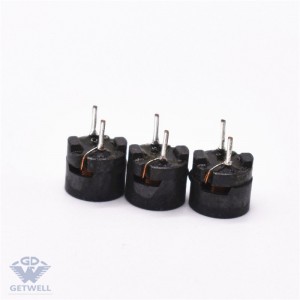
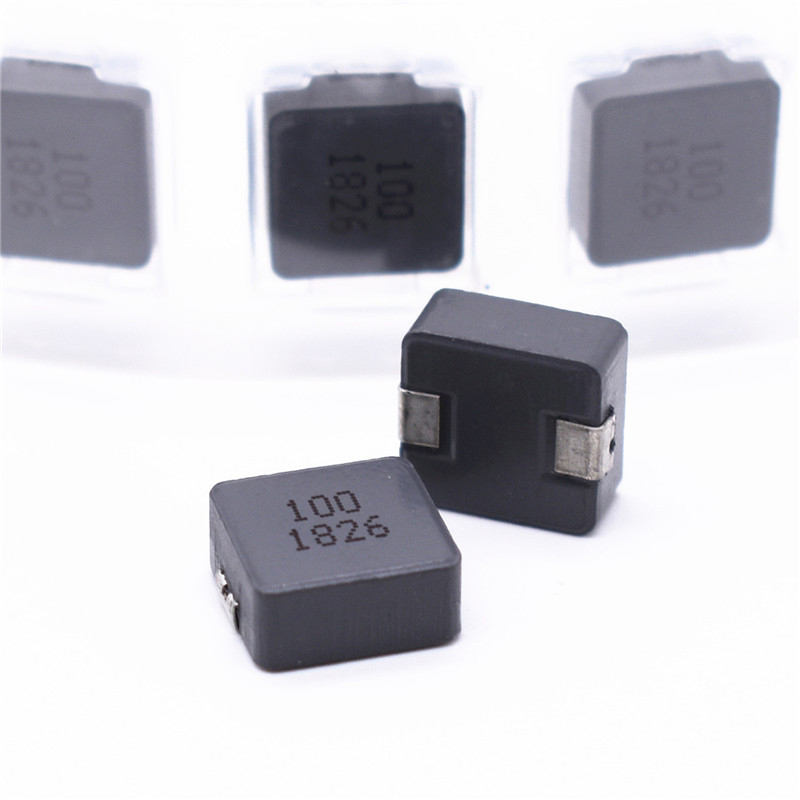
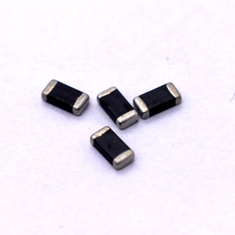
Specializing in the production of various types of color ring inductors, beaded inductors, vertical inductors, tripod inductors, patch inductors, bar inductors, common mode coils, high-frequency transformers and other magnetic components.
Post time: Mar-24-2022