


Custom inductor manufacturer tells you
What role does the patch inductor coil play in the circuit? Are the characteristics and characteristics of the patch inductor the same? Today, let's find out about it.
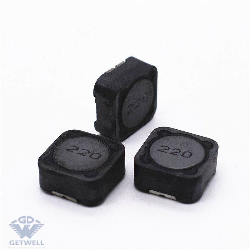
The function of Hollow Inductance Coil
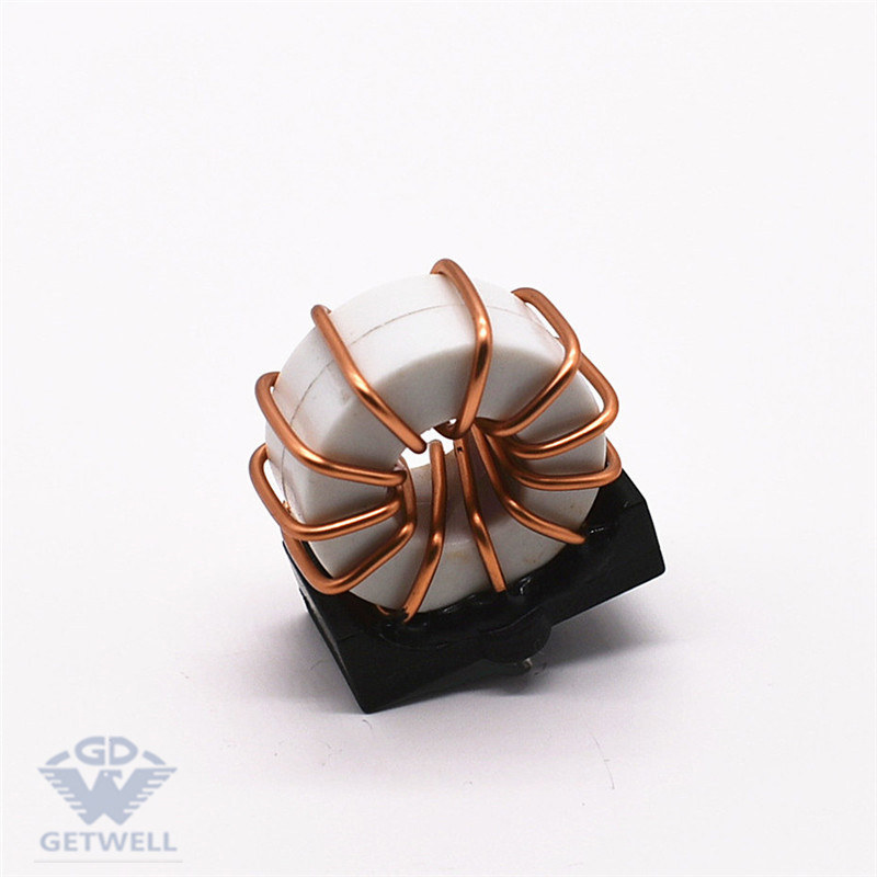
Working principle of iron core inductor coil:
The inductance coil is the ratio of the magnetic flux in the wire to the current that produces alternating flux inside and around the wire when the AC current passes through the wire.
As the DC current passes through the inductor, there is only a fixed magnetic force line around it, which does not change with time. But when alternating current passes through the coil, it is surrounded by magnetic lines of force that change over time. According to the analysis of law electromagnetic induction law, the changing magnetic line of force will produce induced potential at both ends of the coil, which is equivalent to a "new power supply". When a closed loop is formed, the induced potential produces an induced current.
Lenz's law knows that the total amount of magnetic force lines produced by induced current should be prevented from changing the original magnetic force lines as far as possible. Because the original change of magnetic force line comes from the change of external AC power supply, objectively speaking, the inductor coil has the characteristic of preventing the change of current in AC circuit. Inductance coil is similar to inertia in mechanics, which is called "self-inductance" in electricity. Usually, sparks occur at the moment when the knife switch is turned on or on. This is caused by the high induction potential produced by the self-induction phenomenon.
Vulcanization mechanism of patch resistance
The surface electrode is silver electrode, the intermediate electrode is nickel coating, the external electrode is tin coating, the surface electrode material is metal conductor, the secondary protection coating is non-metallic non-conductor, and the electrical coating in the boundary area is very thin or does not form a conductive layer. in particular, the boundary of the screen printing second protective layer is irregular, and the substrate / it is the weakness between the secondary protection and the electrode coating. The sulfur corrosion gas permeates to the surface of the electrode through the layer between the secondary protective electrode and the boundary, and combines with the silver sulfide on the electrode surface to form a compound Ag2S. The low conductivity makes the resistor lose its conductive ability and fail.
In order to avoid resistance vulcanization, the best way is to use anti-vulcanization resistance. By expanding the design size of the secondary protection coating and covering the bottom electrode with the secondary protection to a certain size, the Ni layer and Sn layer are easy to cover the secondary protection layer during electroplating. This avoids the direct exposure of the edge of the relatively weak secondary protective coating to the air environment and improves the vulcanization resistance of the product.
The design idea is from the point of view of packaging and coverage. The anti-vulcanization design uses carbon-based conductive resin adhesive to cover the surface electrode and extends to the secondary protective layer. Another anti-vulcanization design is from the point of view of materials, such as increasing the content of palladium in the surface electrode Ag/Pd slurry and increasing the content of palladium (mass fraction) from 0.5% to more than 10%. Due to the increase of palladium content in the slurry, the stability of palladium improves the ability of resistance to vulcanization. Experiments show that this method is effective.
Generally speaking, there are two ideas for anti-vulcanization design, one is from the point of view of encapsulation, the other is from the point of view of materials. Relatively speaking, in terms of material, it is better to ensure that the resistance is not vulcanized. The PCB board assembly is coated with three anti-lacquers and a protective film is added to isolate the air and prevent resistance vulcanization. Wholesale patch resistor.
Compared with ordinary products, the anti-vulcanization resistance is printed with a layer of thermal conductive polyurethane filling adhesive, which plays a protective role.
The power supply of the fully enclosed glue filling module adopts a full six-sided package structure. This method needs to be tested in practice because the module power around its outgoing pins, that is, the pins, is not really completely turned off. Another solution is to use a true airtight design, where the power supply of the module is filled with nitrogen or argon and is mainly used in military or aerospace products. Because silica gel can adsorb sulfides, another method is to give up filling silica gel and adopt open structure. The open structure should be considered comprehensively from the aspects of improving power conversion efficiency, uniform heat distribution and forced heat dissipation. At present, although the open structure module power supply is vulcanized, the vulcanization risk of the power supply is greatly reduced compared with the modules using filled silica gel. The ceramic substrate power module samples the ceramic substrate and prints the resistance directly on the ceramic substrate. The ceramic substrate has good thermal conductivity. However, the ceramic substrate must be coated with three anti-paint to prevent silver from moving under the action of high temperature, high humidity and electric field force, so as to avoid short circuit between lines. The IC package power supply adopts IC package power supply. Due to the IC package power supply and IC chip, good sealing, the thick diaphragm resistance of the internal power contact can completely isolate the external sulfur gas.
The above content mainly analyzes the function of the chip inductor coil and the resistance vulcanization mechanism. Through the introduction of GETWELL technology, I believe you will have a more in-depth understanding of the chip inductor. If you want to know more about the chip inductor, please feel free to contact us.
You May Like
Read more news
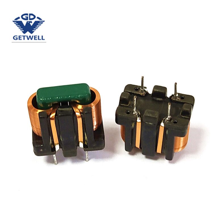
Specializing in the production of various types of color ring inductors, beaded inductors, vertical inductors, tripod inductors, patch inductors, bar inductors, common mode coils, high-frequency transformers and other magnetic components.
Post time: Mar-10-2022