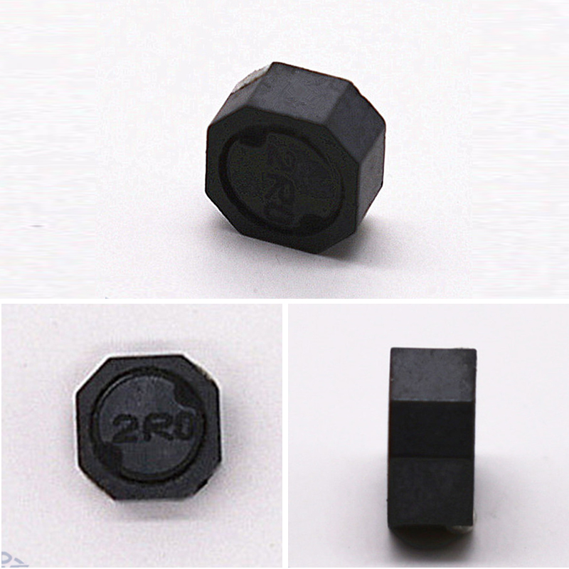
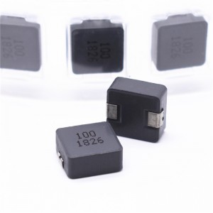
In the chip common mode inductor, different products can be selected according to the characteristics and size requirements. Gv Electronics, a chip inductor factory, shares with you how to select the right COMMon-mode choke coil from a characteristic point of view.
You May Need These Before Your Order
1. How to use differential transmission and common mode choke coils
Before explaining the characteristics of common mode choke coils, let's first introduce the concept of common mode signal and differential mode signal.
Differential transmission is a method used for high-speed data transmission. For example, MIPI? used in the camera and display screen of smartphones, HDMI?, DisplayPort, and USB of computers are all differential transmission methods.
In the two lines of differential transmission, the phase of each other (indicating the deviation of the voltage waveform and the current waveform) is reversed signal transmission.
This signal is called a differential mode signal, and data transmission is performed through the differential mode signal. (Differential mode is sometimes referred to as normal mode). Compared with differential mode signals, there is also a signal called common mode signal, which is transmitted in the same phase in 2 lines.
For chip common mode inductors for signal lines, the common mode signal is an unwanted signal, that is, noise, which is called common mode noise.
Differential mode signals are mixed with common mode noise. When a differential signal is received, the differential mode signals reinforce each other, and the common mode noise cancels each other out. Differential transmission methods like this are less susceptible to common mode noise.
The differentially transmitted radiation signals are observed at a distance, and the signals are superimposed on each other. At this time, the differential mode signals cancel each other out, and the common mode noise strengthens each other. That is, it is susceptible to common mode noise at a distance.
When similar noise problems occur, the common mode choke coil is connected in series to the differential transmission line to effectively remove the common mode noise.
2. Insights into the characteristics of common mode choke coils
In fact, the differential mode noise is somewhat reduced due to the common mode choke coil. In addition, differential-mode and common-mode signals experience different reductions due to different frequencies. The characteristics of such a common mode choke coil are represented by the frequency characteristics of the differential mode insertion loss Sdd21 and the common mode insertion signal Scc21. (Sdd21 and Scc21 are part of the mixed-mode 4-port S-parameters)
Frequency characteristics of common mode insertion loss Scc21. The deeper the insertion loss, the greater the loss. The higher the frequency of the differential mode signal, the greater the loss. The common mode insertion loss Scc21 is a curve with a peak, and the effect of removing common mode noise varies depending on the frequency.
The signal frequency of the chip common mode inductor for signal line varies depending on the interface method, and the common mode choke coil also changes accordingly.
Whether the common mode choke coil is suitable can be judged according to the transmission signal waveform. Generally, the cut-off frequency of the common mode choke coil is three times the signal frequency of the differential transmission specification. The so-called cutoff frequency is the frequency at which the differential mode insertion loss becomes 3 dB.
However, even if it is less than 3 times, there are many problems in the signal waveform, and this is a reference at best. (Because the standard of signal quality such as perforation map is stipulated on each interface, it is finally judged whether it is suitable or not according to this standard)
On the one hand, the problem noise and its frequency vary from terminal to terminal, and accordingly the frequency characteristics of the appropriate common-mode insertion loss change accordingly.
For example, when noise occurs that exceeds the limit value specified by the emission regulation standard, it is more effective to select the one with larger common mode insertion loss in the frequency band of that noise.
In addition, common mode noise reflected by differential transmission may adversely affect its own wireless communication functions such as LTE and Wi-Fi. It can be considered that the common mode noise of the same frequency as the wireless communication occurs, and the antenna receives this noise. This is called suppressed reception sensitivity. At this time, by inserting a common mode choke coil, the emission of common mode noise can be suppressed and the reception sensitivity can be improved.
The above is an introduction to the characteristics of SMD common mode inductors. If you want to know more about SMD inductors, please contact us.
pecializing in the production of various types of color ring inductors, beaded inductors, vertical inductors, tripod inductors, patch inductors, bar inductors, common mode coils, high-frequency transformers and other magnetic components.
Post time: Sep-27-2022


